
OptimAir-S / OptimAir-L
Main features
• Chilled and climate beam for flush installation in suspended ceilings
• 2-way flexible distribution pattern along the suspended ceiling
• Supplied in versions for either cooling or cooling and heating
• OptimAir-S low-profile variant (155 mm)
• OptimAir-L (installation height 185–222 mm)
• Adjustable nozzles in 7 steps and Airflex air deflectors for a draught-free indoor climate
• Hinged front grille for easy inspection and maintenance
• Can be integrated into the demand-controlled solution ControlAir BAS
• Available as AQUATiQ-OA for DCV system ControlAir SYS
Description
General
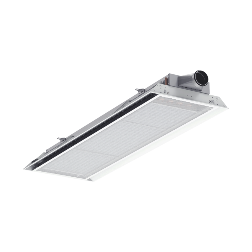
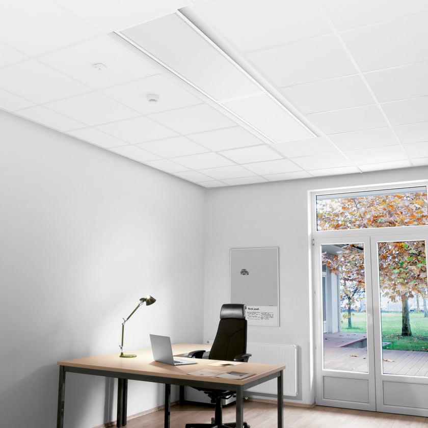
• OptimAir is a two-way induction type active chilled beam, designed for integration in false ceilings.
• OptimAir is primarily designed for supply air, cooling and/or heating in buildings, where a comfortable indoor climate with individual room control is required.
Variants
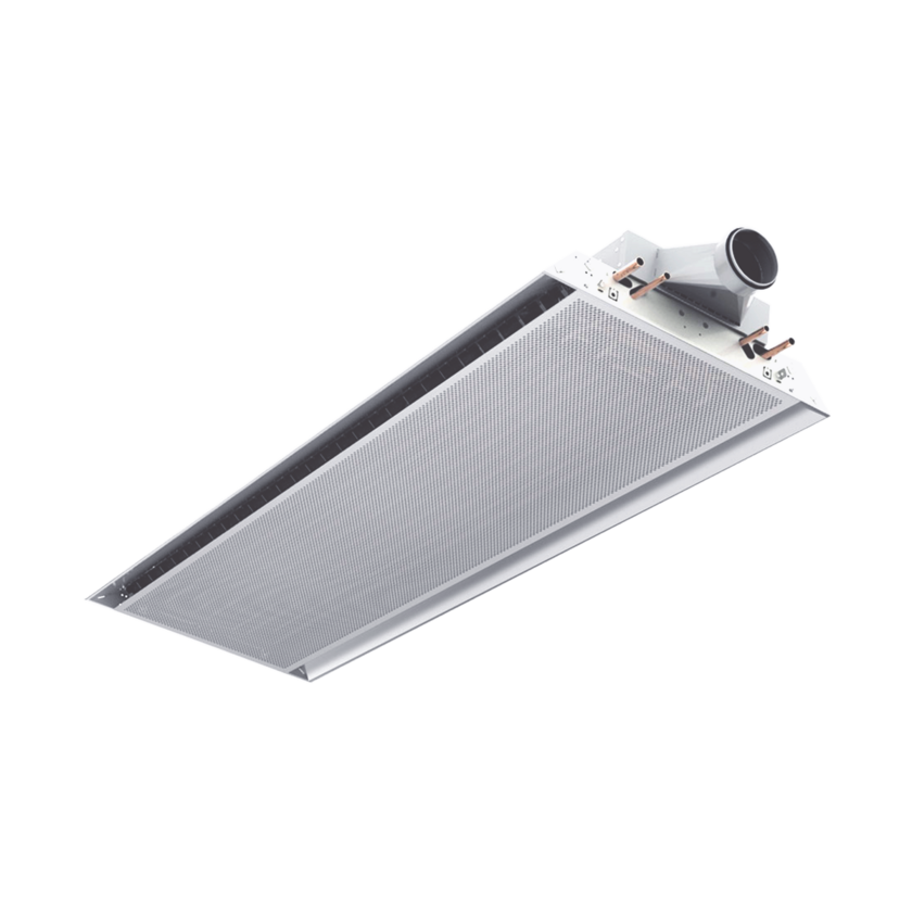
• OptimAir-S (OAS) / AQUATiQ-OAS, low profile version suitable for most airflow requirements.
– Airflows up to 33 l/s at 50 Pa.
– Installation height 155 mm.
– Short side duct connection in Ø100 mm.
• OptimAir-L (OAL) / AQUATiQ-OAS, higher capacity version, suitable for higher airflow requirements.
– Airflows up to 55 l/s at 50 Pa.
– Installation height 185 mm (Ø125) or 222 mm (Ø160) with two duct connection configurations:
– Single short side connection, Ø125 or Ø160 mm.
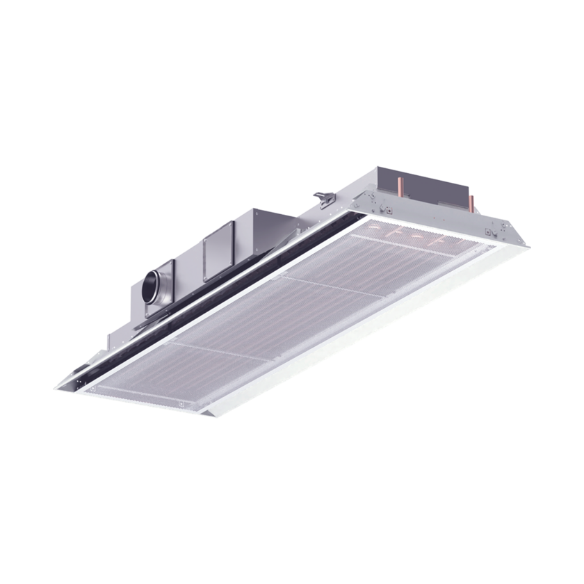
– Single or dual long side connection, Ø100 or Ø125 mm.
– The number of duct connections depends on the product length, primary airflow rate and pressure requirements of the selected chilled beam.
• The unit also offers two coil (heat exchanger) options to best suit cooling and/or heating
demands of the occupancy zone.
• The unit is designed to fit standard 600 mm suspended ceiling frameworks, with additional adaptation possibilities to fit most suspended ceiling systems on the market.
• OptimAir is equipped with AirFlex supply air deflectors. Each deflector can be individually adjusted, providing for a variety of easily adjusted spread pattern settings in order to achieve a draught-free indoor climate.
Functionality
• The primary air flow is injected into the plenum box of the beam and distributed
through the supply air nozzles.
• The air is discharged through the nozzles above the coil which creates a low-pressure zone. This low-pressure zone draws ambient room air through the return air grille and into the coil.
• As the return air passes the coil fins, the air is conditioned (i.e.cooling alt. heating), according to the water temperature flowing through the coil.
• The conditioned air then mixes with the injected supply air before it is discharged back into the occupied zone.
• The mix of supply air with conditioned return air is discharged along the ceiling provides an optimal Coanda effect that is always the objective when the occupied zone requires low air velocities.
• The standard version of OptimAir is supplied with adjustable nozzles. With the use of an Allen key the airflow can be adjusted in seven steps on each side of the beam. This feature simplifies setting and re-adjustment of the nozzle positions in the event of changed flow requirements.
Material options and finishes
• Powder coated finish.
Sizes (mm)
OptimAir-S (OAS) low-profile variant:
• Supplied in 4 different lengths: 1200/1800/2400/3000 mm.
• Supplied with single short side duct connection Ø100.
OptimAir-L (OAL) higher capacity variant:
• Supplied in 5 different lengths: 600/1200/1800/2400/3000 mm.
• Supplied with single short side duct connection Ø125 or Ø160 mm.
• Supplied with single or dual long side duct connection: 1x Ø100 / 1x Ø125 / 2x Ø100 / 2x Ø125.
Configuration alternatives
• Chilled beam version for cooling or Climate beam version for cooling and heating.
• Selectable water connection option for beams with short side duct connection:
– Same as the air duct or opposite side of the air duct connection.
• Selectable top-entry water connections for beams with long side duct connection:
– Left or Right short side of the air duct connection.
• Available in versions with 1 or 2 cooling water circuits.
• Adjustable nozzle strips, 7 different positions, 1 per side lengthwise.
Please see the product sheet for detailed information.
Options
• Standard product variants are supplied for installation in suspended ceiling grids / modular ceiling systems, 600 × 600 mm.
• For free-hanging installation, a Coanda rail is available as an optional extra.
• For installation in fixed ceilings, a plasterboard frame is available as an optional extra.
Demand-controlled solutions
• The chilled beam can be integrated into the ControlAir BAS system for simple demand-controlled solutions. Alternatively, it can be used in both stand-alone VAV solutions and third-party solutions with central supervisory control. For further information, see the separate ControlAir BAS Design Guide (SE/DK).
• The product is also available in the AQUATiQ-OA version for hybrid solutions, as a component of DCV system ControlAir SYS. Contact our sales for further information.
Accessories
The product can be supplied with a range of accessories for installation in both stand-alone VAV solutions and systems with central supervisory control:
Balancing dampers with measuring rail:
– ZMC balancing damper.
– BASiQ VAV/CAV damper.
Butterfly dampers with minimum-flow bypass for lower noise levels than conventional dampers:
– SPD.
Straight control valves for thermal actuators:
– BAS-SV-DN12 (DN15)
– BAS-SV-DN15 (DN12)
Transformer:
– BAS-TR-20VA – 24 V AC, 20 VA.
– BAS-TR-60VA – 24 V AC, 60 VA.
Thermal actuator, 24 V on/off:
– BAS-ST-NC (normally closed)
– BAS-ST-NO (normally open)
Valve adapters in several versions: VA 54, VA 78, VA 80.
• Device housing and duct connection made of hot-dip galvanized sheet steel with EPDM rubber gasket.
• Visible parts: casing, frame and perforated front grille made of sheet steel, powder coated in white RAL standard colour. Other colours are available.
• Coil made of copper tubes with aluminum slats.
• Plastic details of Polyethylene.
• For more information about standard materials and colors, see the separate document Product specification which can be downloaded from our website.
• The following information is only a general overview of the of assembly, installation and adjustment procedure. Always refer to the product's operation and maintenence documention (DU-SE/DV-DK) for detailed installation instructions, inluding commissioning, nozzle strip adjustment and setting options for Airflex air deflectors.
• The product is connected to a circular supply air duct. Connection to a straight mounted flexible duct is not recommended.
• Heating and cooling water pipes are installed by a plumbing contractor.
• The unit is supplied with 4 factory-fitted suspension brackets for pendants (one in each corner). Fittings with pendants can be adjusted separately in four directions.
• The product can be suspended using a threaded rod or mounted directly against the ceiling.
• Ensure that no damage occurs to the cooling/heating coil when tightening valves and connections. To avoid this, always use a suitable wrench as counterweight.
• When installing the beam, space should be reserved for opening the front grille and accessing the device for cleaning, inspection and service.
• In order to be able to adjust the operating pressure, the product should be preceded by an comissioning damper mounted in the duct before the unit, e.g. ZMC or SPD, but not an iris-type damper.
• When installing the commissioning damper, requirements for the preceding straight section should be taken into account, see the specific damper's documentation for detailed information.
• The supply air flow, q (l/s or m3/h) is checked by measuring the operating pressure P (Pa) in any nozzle over the nozzle strips or over the measuring rail of the commissioning damper. When the prescribed operating pressure has been measured, the required air flow has been achieved.
• For calculation of K factors, see tables and calculation formula in the operation and maintenance document (DU/DV) of the beam. For K factors with a commissioning damper, please refer to the documentation of the specific damper to be used.
• When the unit is supplied with control options, the product is delivered internally pre-wired from the factory. See separate documentation depending on the current option regarding wiring, commissioning and operation of control and powering components.